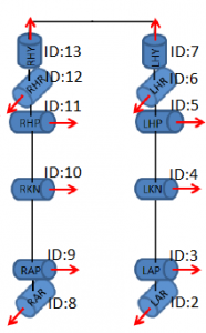
Each dynamixel needed to be configured with its own separate IDs. They also needed to have there maximums set so that the servo would not attempt to go past the physical barriers of it base. To make things easier for ourselves, we used the same naming scheme that was used by the Hubo 2. Below you will find the rotation diagram and the added dynamixel ID of each joint:
